

News Center
How the transformer works
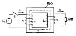
The transformer consists of a core (or core) and a coil. The coil has two or more windings. The winding connected to the power supply is called the primary coil, and the other winding is called the secondary coil. It can change the AC voltage, current and impedance. The simplest core transformer consists of a core made of soft magnetic material and two coils of different numbers placed on the core, as shown.
The role of the core is to strengthen the magnetic coupling between the two coils. In order to reduce the eddy current and hysteresis loss in the iron, the core is laminated by a lacquered silicon steel sheet; there is no electrical connection between the two coils, and the coil is wound by an insulated copper wire (or aluminum wire). One coil is connected to the AC power source called the primary coil (or the primary coil), and the other coil is called the secondary coil (or the secondary coil). The actual transformer is very complicated, and copper loss (coil resistance heat), iron loss (core heat generation), and magnetic flux leakage (air-closed magnetic induction line) are inevitably present. For the sake of simplicity, only the ideal transformer will be described here. The ideal transformer is established by ignoring the leakage flux, ignoring the resistance of the primary and secondary coils, ignoring the loss of the core, and ignoring the no-load current (the current in the coil of the primary coil of the primary coil). For example, when the power transformer is running at full load (the rated output power of the secondary coil), it is close to the ideal transformer.
The transformer is a stationary appliance made by the principle of electromagnetic induction. When the original coil of the transformer is connected to the AC power source, an alternating magnetic flux is generated in the core, and the alternating magnetic field is represented by φ. φ in the primary and secondary coils are the same, φ is also a simple harmonic function, and the table is φ=φmsinωt. According to Faraday's law of electromagnetic induction, the induced electromotive force in the primary and secondary coils is e1=-N1dφ/dt, e2=-N2dφ/dt. In the formula, N1 and N2 are the number of turns of the primary and secondary coils. It can be seen from the figure that U1=-e1, U2=e2 (the physical quantity of the original coil is indicated by the lower corner 1 and the physical quantity of the secondary coil is indicated by the lower corner 2), and the complex effective value is U1=-E1=jN1ωΦ, U2=E2=-jN2ωΦ, Let k = N1/N2, called the transformer's ratio. From the above formula, U1/U2=-N1/N2=-k, that is, the ratio of the effective value of the transformer primary and secondary coil voltages is equal to its turns ratio and the phase difference between the primary and secondary coil voltages is π.
Further, it is concluded that:
U1/U2=N1/N2
In the case where the no-load current is negligible, I1/I2=-N2/N1, that is, the effective value of the primary and secondary coil currents is inversely proportional to the number of turns, and the phase difference is π.
Further available
I1/ I2=N2/N1
The power of the original transformer and the secondary coil is equal to P1=P2. Explain that the ideal transformer itself has no power loss. There is always a loss in the actual transformer, and its efficiency is η=P2/P1. The efficiency of power transformers is very high, reaching more than 90%.